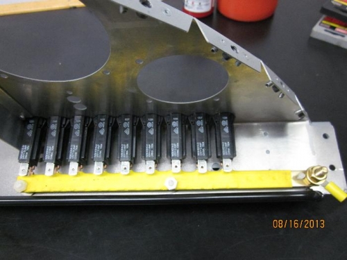
Used shrink tube around the positive bus for insulation. The bus is drilled/tapped and secured to the panel with 1/4" nylon standoffs and (3) #8 nylon screws. With the connection to the panel mounted circuit breakers the bus is very secure. Installed a 1/4-20 bolt in the end of the bus for the positive power feed. There are (4) 10-32 screws available for future power connections. In the first picture the bus is installed and plugged into the breakers.
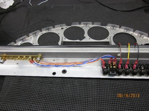
Used the bus bar from an ElectricalHub.com M440 common busbar assembly for the instument ground bus. It is mounted under the panel, to the left in the second picture. The braided line from the battery will connected at the left end in the picture with provided 1/4-20 hardware.
I'm using a thermal wire stripper on the wire insulation. This helps prevent nicking the strands on the wire. I've heard these, or something similar, are required for NASA and mil-spec work. Started wiring the master solenoid and mag grounds and the switches from the breakers. The looped wire from the breakers to the switches can be seen in the right of the second image. Jumper loops are about 3.5" long. I used some automotive door edge guard strips on the lip of the panel to protect the wires.